Tracing Journal: Xotic AC Booster, RC Booster and Bass RC Booster
Xotic is a notorious company among the DIY pedal scene. Their pedals are massively popular despite being somewhat unoriginal, little more than Tube Screamers and Bluesbreakers with a Baxandall tone stack, and they really do sound great. But they also—up until recently—partially gooped their PCBs and sanded the markings on their ICs to make reverse-engineering difficult. On top of that, they often quietly make changes to the circuits, whether due to constant tone-tweaking or just parts availability during manufacturing.
The result is that the DIY community has traced several Xotic pedals, but almost every schematic is slightly different, and it’s very hard to sort out which of the differences are due to circuit changes by Xotic or just due to inaccurate traces.
When I first developed the Malacandra project in 2018, I gathered as many of the schematics as I could find and compared them to try to come up with a “consensus” schematic, the most accurate combination of all of them. At the time, I didn’t realize accuracy was a moving target with Xotic due to the frequency of revisions. But, when we got the opportunity to trace a few Xotic pedals directly, we decided to clear it up once and for all.
We traced three pedals that share the same PCB in Xotic’s production line: the AC Booster, RC Booster and Bass RC Booster. The AC Booster and Bass RC Booster were purchased new in 2019, while the standard RC Booster was used but only a couple of years old.
The schematics were indeed different from the community’s prior traces. None of our traces matched any of the known schematics exactly. The topography was all the same, no huge revelations there, but each of them had some new part variations that hadn’t been seen before.
Here’s the thing, though: this doesn’t mean that earlier traces by the community are inaccurate. I just felt like we needed some sort of definitive trace to satisfy my own desire for accuracy so there were no lingering questions, and so I could say that at least these schematics were accurate to these units.
So: let’s get to it!
Note: Not shown in these schematics are the bypass switching arrangement (which is standard 3PDT true bypass) or the bypass indicator LED. Xotic does use some extra circuitry around the LED, possibly to prevent it from popping when the effect is turned on and off, but it’s unimportant to the functioning of the effect. Only the main circuit and power sections are shown.
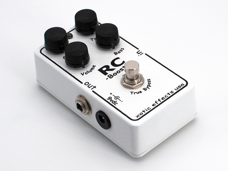
Xotic AC Booster
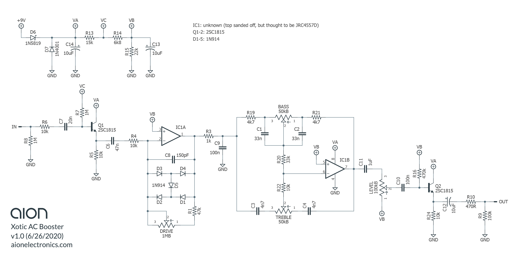
The biggest thing to note about the AC Booster is the diode arrangement with D5 bridging the two pairs. Other traces show two diodes in one direction and one in the other for an asymmetric clipping arrangement similar to the Boss OD-1. Based on photos of earlier AC Booster pedals, it appears that the diode configuration was changed. Earlier traces were probably correct and Xotic intentionally changed the diode configuration along the way.
Also note the 1-meg drive pot. Earlier versions used 500kB which means they’d have less maximum gain available.
The last change is C6, which is 100n in earlier traces but has been changed to 47n. This will raise the low-cut frequency of the clipping stage for slightly less bass.


")


")
Xotic RC Booster
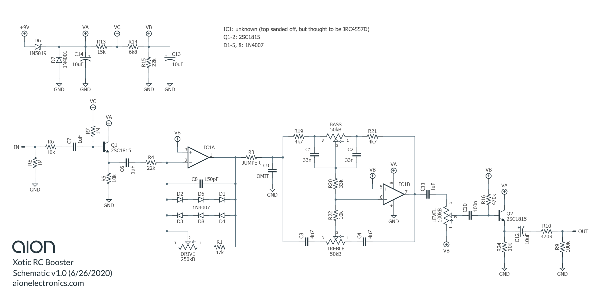
This one is closer to the known traces than the AC Booster, but note the 1uF value for the input capacitor where other schematics show 47n. It likely won’t make a huge difference since 47n is plenty big enough for an input capacitor.


Xotic Bass RC Booster
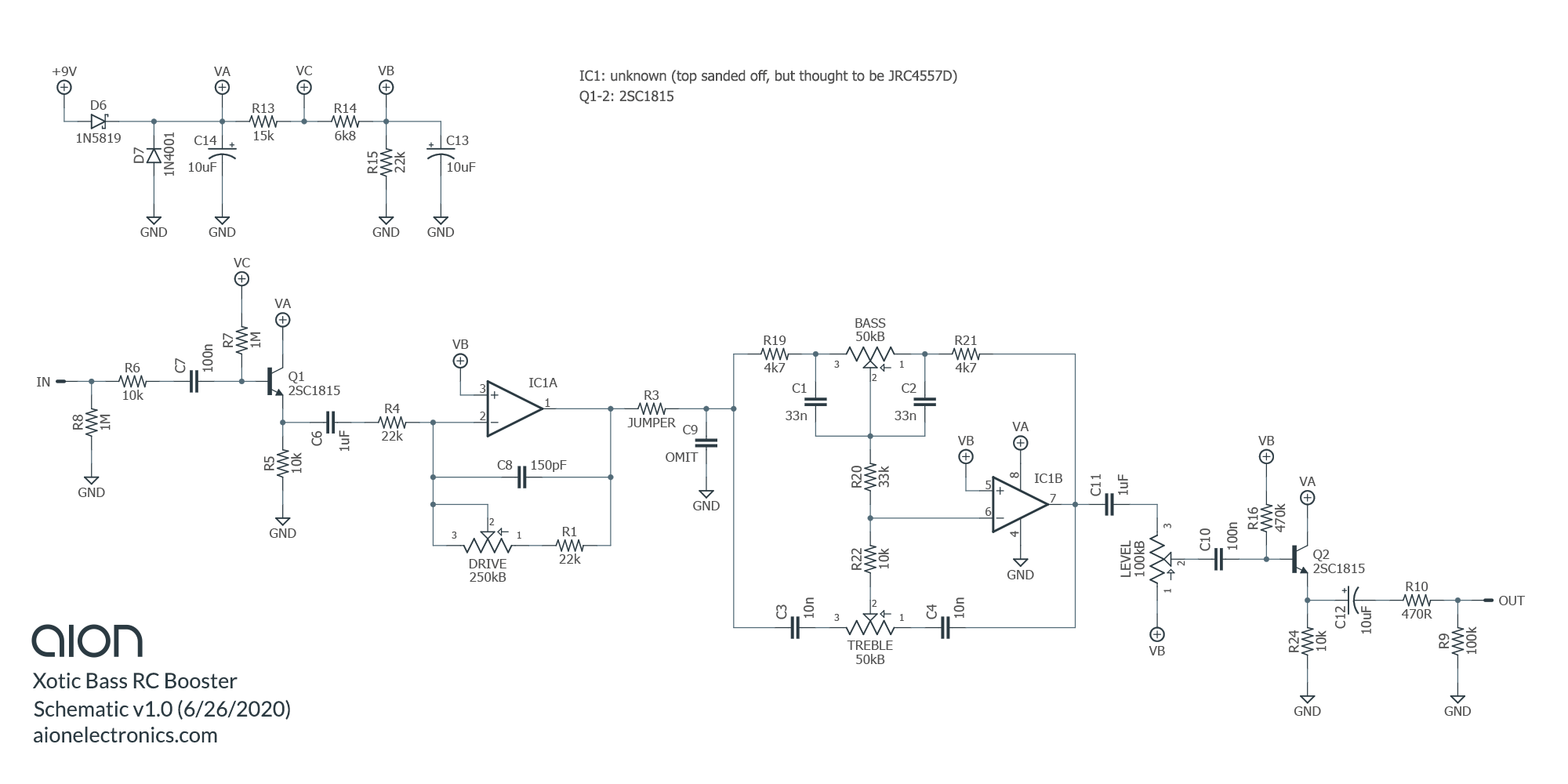
I’m not aware of anyone who’s taken apart a Bass RC Booster, so this is a brand new trace, although as you can see there’s not much that’s changed from the standard RC Booster. All clipping diodes have been removed, the bass tone capacitors C3 and C4 have been doubled from 4n7 to 10n, and the minimum-drive resistor R1 has been dropped from 47k to 22k. Also, for some reason, the input capacitor C7 has been lowered from 1uF to 100n, although either of these values will still provide full-frequency operation for either bass or standard guitar.
Note that this was version 1 of the Bass RC, not the newer version 2 with a second gain-boost footswitch. The footswitch is likely just switching between two gain potentiometers, similar to the Fulldrive, but we haven’t looked inside one to know for sure.

")
")
")
")
")
")
")
Malacandra V2
Version 2 of the Malacandra Boost / Overdrive is releasing today, fully replacing the first version. The main change to the PCB layout is the way the diodes are configured, adding a seventh diode as a “bridge” between the two sets, used in the AC Booster. The bias supplies were also changed slightly, although this likely wouldn’t affect the sound of the unit. The documentation has been updated with part variants for all three versions.